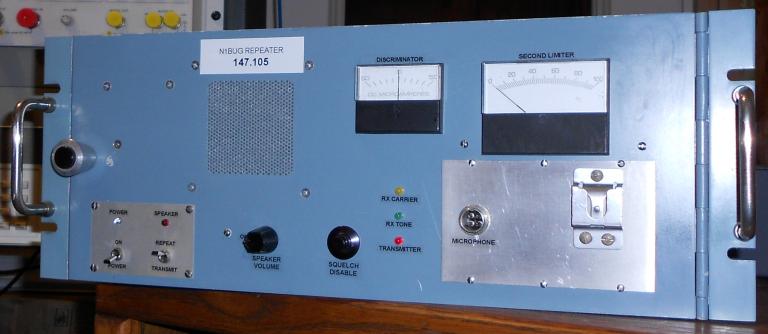
Updated front panel, August 2015
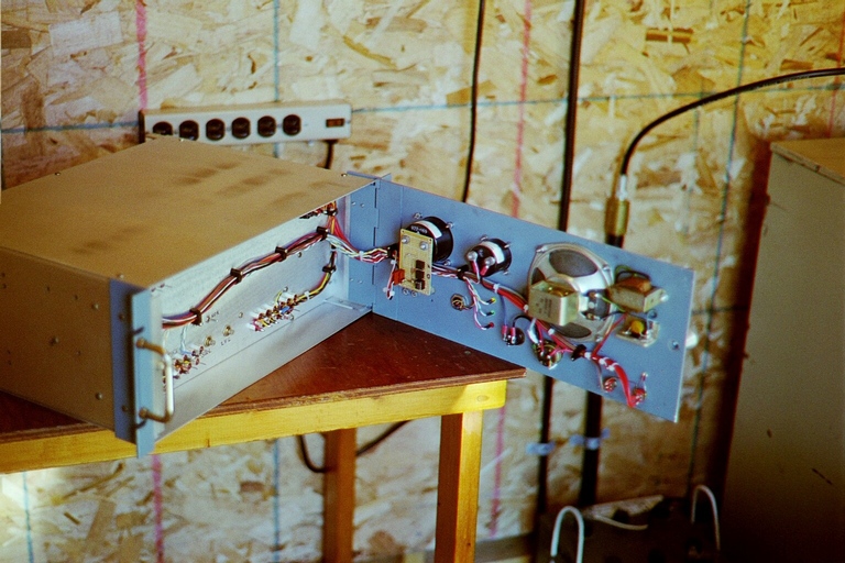
Behind the front panel
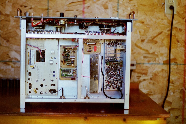
Receiver (left) and transmitter compartments
Controller compartment
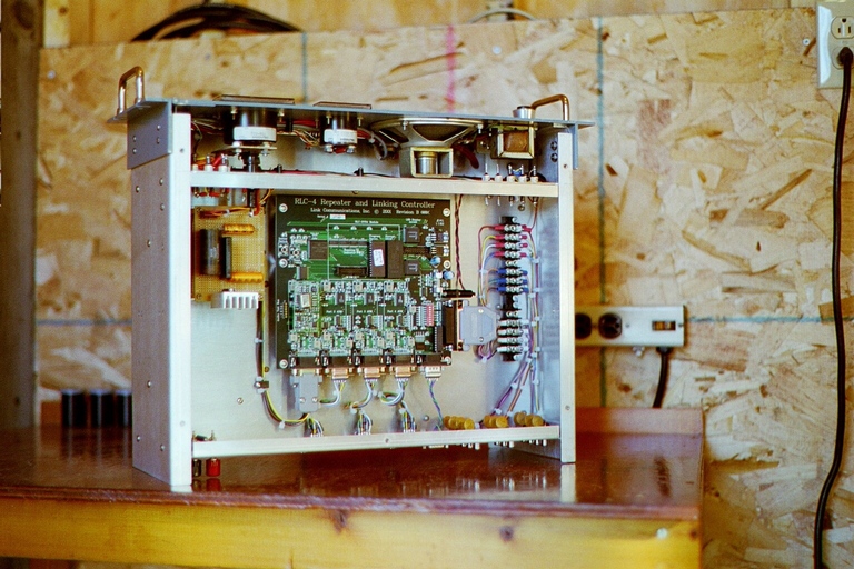

The repeater uses repackaged GE and other components with custom features added. The receiver is a modified GE Executive series. A home built squelch based on the famous Motorola squelch chip from a Micor has been added, along with a Communications Specialists TS-32 tone decoder and home built tone filter to remove the incoming CTCSS tone. The exciter is a modified GE MASTR II of the PLL variety. It drives a 25 watt amplifier salvaged from an old KDK 2-meter transceiver. Tone encoding is handled by a Communications Specialists TS-64. Signal strength and discriminator meters, special control circuitry, controls and indicators have been incorporated in the design. The repeater also has provision for adding a voter, should we ever gain access to sites that would allow us to deploy additional receivers. The repeater controller is a Link Communications RLC-4 housed in the repeater cabinet. Port 1 of the controller is internally wired to the 2 meter receiver and transmitter, while ports 2 through 4 are wired to DB9 connectors on the repeater rear panel for connection to external repeaters, links, or whatever might be desired in the future. Primary power is supplied by two DuraComm RM5012 supplies which have been combined to provide for the high current demand of this system. A home built 20 amp supply serves as a battery charger. There are two deep cycle batteries capable of sustaining the system at full power for at least two days of normal operations.
A Henry C250AB30R amplifier is used to boost power to approximately 175 watts. There is an impedance matcher between the amplifier and duplexer to eliminate any reactance presented by the duplexer.
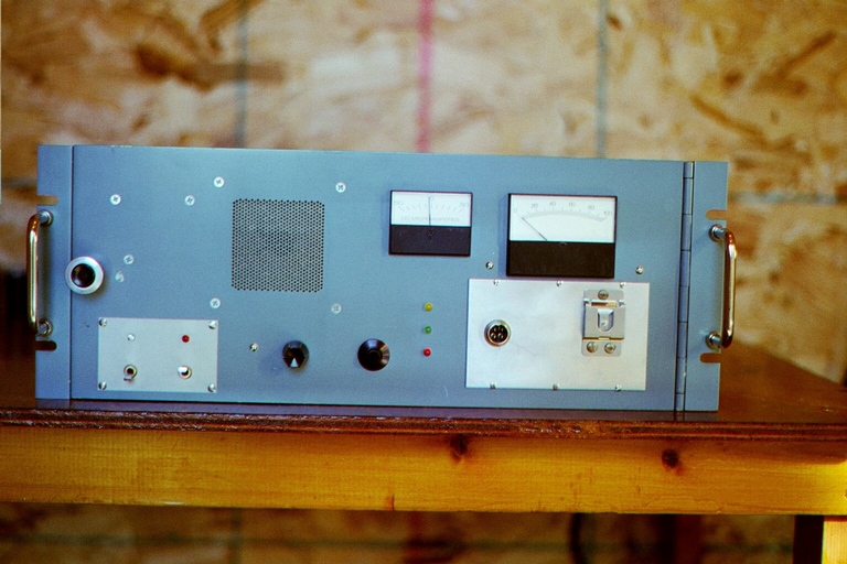
Front panel
Updated front panel, August 2015
Behind the front panel
Receiver (left) and transmitter compartments
Controller compartment
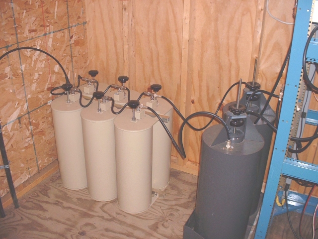
A Decibel Products DB4062B six cavity duplexer provides receive/transmit isolation, allowing the use of a single antenna for both transmit and receive. Two additional Decibel Products 11 inch pass cavities shown here (one in the receive path and one in the transmit path) were added to prevent interference from or to a nearby APRS digipeater. After refurbishing the duplexer these were found to be unnecessary and have since been removed. For many years there was a home built GaAsFET preamp between the receive side pass cavity and the receiver. As the site has become more busy the noise floor has risen, making the preamp ineffective. It has been removed.
Duplexer and pass cavities (pass cavities no longer in the system)
The feedline is approximately 135 feet of LDF5-50A (7/8 inch) heliax. The antenna is a Telewave ANT150F6 collinear. The base of the antenna is 105 feet above ground.
Antenna - click for high resolution image (PARC photo)

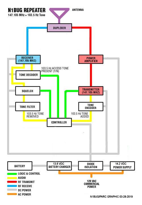
Here is a block diagram showing the basic system configuration.
Last update April 21, 2019